Wednesday, October 22, 2014

Tail feathers and covering


A lot has happened since the last update in July. Mainly the tail feathers ( almost literally ) are done now and the fuselage and tail is covered, ready for painting. Aluminum fuselage side panels are ready for painting as well.


August- September 2014 


Had to purchase 250 pieces of bamboo from an importer and sort through them to find enough good ones. Requires 3/4 inch and 1 inch sizes, up to 10 foot long ones.  


The adapter to accept the center bamboo post
 
Joined the wood strips to the bamboo using T88 epoxy.
 

Getting ready to wrap the wood strips and bamboo poles where they meet.  Used the NEW Super Seam cement and ceconite tapes.


T88 epoxy


wood strips merged with the bamboo

Tail center bamboo adapter

gluing everything in place with T88

leveling

leveling

If you look closely you can see the nine elevator wires, top and bottom. This is in the most forward control position. Reason for all the tapes is to prevent the poles from splitting.
 
cable splitter from the two elevator cables to the nine wires going to the bamboo poles

getting ready to secure the wires
 

some show completed.

looking to the rear, underneath

top view, across

Nodes where the eyelets will get attached to. Lock nut is embedded in the epoxy.  

Tip node

Looking forward
 
from below, looking forward

from above, looking forward 


Upper elevator cable and splitter.
 

September-October 2014

Now comes the fun of covering.
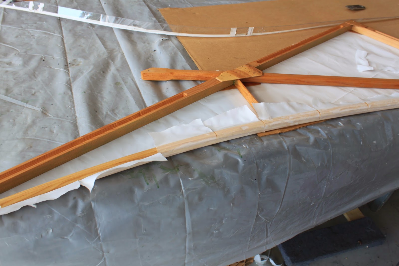
 This is where I deviated from the original version, which used linen, coated with Cellon. I assume that was a version of cellulose at that time. Unfortunately it only had a two year life span.  After much thinking and research I decided on AC grade Ceconite SF102, 2.7 oz. , after all I want it to last a lot longer.


Starting with the upper fin
 
 
step 2
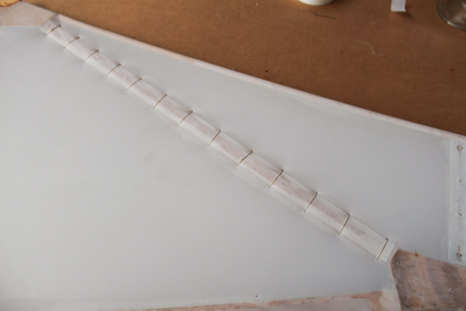
 
Rib stitching- back side
 
 
close up
 
All by the book,
 
By the bible
 
right side fuselage gets started
 
elevator already covered
 
starting on left side
 
more of left side


Tail from below, held on with 1/2 inch double sided  seamstick tape and then rib-stitched
 
More of the elevator
 
Inspection panel open, seen from front


Open seen from back
 
Closed
 
Quarter turn closure fastener
 
Tail from above, before tensioning


Tail from below, note the merge of double layer to single layer. Glued and rib-stitched
 
Outriggers in place and tail now stretched
 
Whole section with outriggers
 
 
Better view of tail with outriggers. Lots of rib stitching!


Coming up: Painting, rest of the rigging wires and final assembly, taxi under own power?

Now if I only had wings !


Wednesday, July 2, 2014


July 1 2014 update


With the help of several very qualified and helpful individuals, I was able to modify the oil system in order to allow me to turn the engine upright. The initial running attempt showed that too much oil stayed in the crankcase, the return line level was too high and the result was that oil was expelled via the breather and the labyrinth seal- and wherever else it could.

First, the oil tank had to be repositioned lower, to allow space for the newly planned return lines. This was actually fairly easy, just re-mounted it below the strut, instead of above. As a result the gascolator had to be lowered as well and fuel line re -routed. No big problem.   

Before
 

After
 

Second,  the oil pan had to be removed, which in itself required a special wrench and special prop hub puller. Courtesy Dave Watson of Splitpin Engineering.


Then the oil pan was modified to accept a quicker oil flow for drainage, plus the labyrinth seal return hole was drilled. The outlet was now at the lowest point in the oil pan and included a baffle shield. Thanks to Clark Seaborn from Alberta CA for that input. 
Drain -back holes
 
 
Labyrinth return hole
 

 Drain Flow holes
 
Outlet assembly
 
 
Baffle inside oil pan 
 
 Drain installed in lowest point in pan
 
 
Assembly required again the prop nut socket wrench. Also a special tool to center the labyrinth seal outer ring. Thanks to Mike Maniatis for sharing that tool. 


 I plugged off the previous oil return line, which was the original breather when the engine ran in the inverted configuration. The new return line is still 1" ID, but at the lowest point of the oil  pan. 
 

Plugged off old line
 

Oil pickup with check valve on bottom as before
 
Pre-filter, primed, as before
 
Steel Line to pump, same as before


The breather now runs from the front to a separator, like I had it before, however I am running the vent hose to a temporary oil bottle, so I can monitor the quantity of blow-by, if any. So far none, after one hour running. The drain of the separator is temporarily run into another oil bottle, again, so that I can get a feel of how much is being separated. Looks like a few ounces after an hour of running. Many thanks to Michael Damiani of Golden Air Museum for help on that. 
Breather
 

Separator and vent
 

Check bottle f vent

 Temporary bottle for drain located below vent bottle, allows checking of blow-by amounts, this will later be connected to the brass fitting visible at the top of the oil tank. 
 

Finally everything back together, oil back in, primed, fueled. Run for an hour or more, at various throttle settings,  seems fine, oil stays surprisingly cool.